
We start with Photoshop or other image editing software. (We use Photoshop as our example because it is both widely available and what we use here at Artwork. However if you have a different editing tool, it should be able to perform the same operations.

Normally the image we receive will cover more than a single die. In this case we need to crop the image using Photoshop to include only a single die image. It is usually pretty clear where the "street" is located. I normally crop to the inner edge of the street because the street can also contain test pads that might be confused for bond pads.
Using Photoshop we convert RGB to grey-scale if needed. We can adjust the RGB values to produce as high a contrast image in grayscale as possible. Just because an image looks like it is already in gray-scale does not mean that the internal data is grayscale.
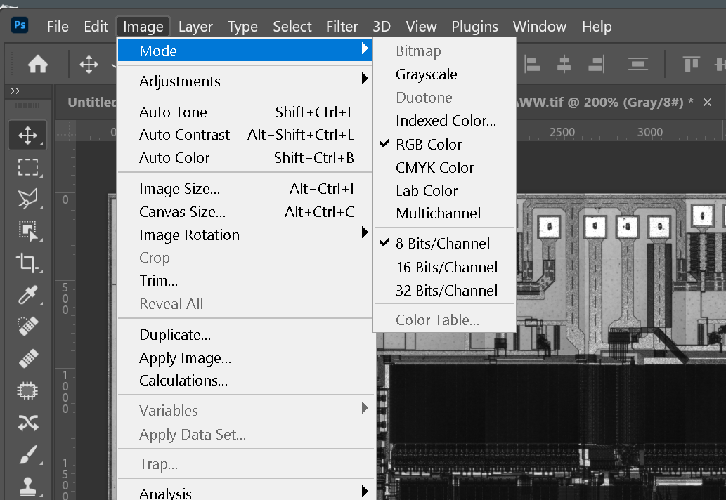
We use Photoshop's Invert command to reverse the polarity so that the die pads are "dark." This is because in the next step we will convert the black pixels into GDSII polygons.

After polarity inversion the die pads are "black"

This is a critical step and requires some care and experience. Using Photoshop's Threshold command adjust the threshold level (determines the boundary in the gray image where pixels go black or white) to insure that the die pads are completely isolated by white pixels from the other ciruitry on the chip surface.

However if you go too far, you may shrink the desired pad or even split one in two.
Examine carefully all the pads at high magnification to insure each is properly isolated.


Once your threshold has been optimally set, convert the resulting image from grayscale to "bitmap" (This is Photoshop's term for a monochrome image.)
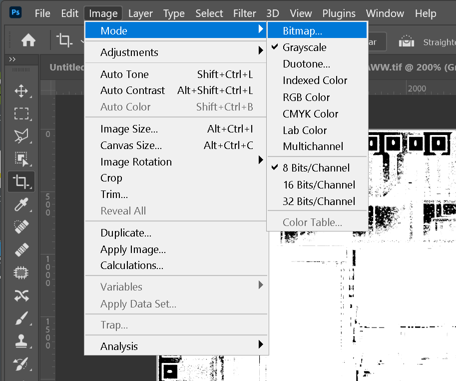
Now that the image mode is bitmap, save as a TIFF output, uncompressed. Since these are now 1 bit/pixel images the resulting file is much smaller than the source RGB or grayscale image.
This monochrome TIFF image (with the die pads "black") is the input to our converter.
